
2.1 Bearing and its function in motor structure
Common power tool structures include motor rotor (shaft, rotor core, winding), stator (stator core, stator winding, junction box, end cover, bearing cover, etc.) and connecting parts (bearing, seal, carbon brush, etc.) and other major components. In all the parts of the motor structure, some bear shaft and radial load but do not have their own internal relative motion; Some of their own internal relative movement after but do not bear axis, radial load. Only bearings bear both shaft and radial loads while moving relative to each other inside (relative to the inner ring, outer ring and rolling body). Therefore, the bearing itself is a sensitive part of the motor structure. This also determines the importance of bearing layout in industrial motors.
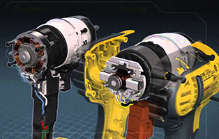
Electric drill analysis diagram
2.2 Basic steps of rolling bearing layout in motor
The layout of rolling bearings in electric tool motors refers to the process of how to place different types of bearings into the system in the shafting when engineers design the structure of electric tool motors. To achieve correct motor bearing arrangement, it is necessary to:
The first step: understand the working condition of rolling bearings in tools. These include:
- Horizontal motor or vertical motor
Electric work with electric drill, electric saw, electric pick, electric hammer and other different types, confirm the motor in the installation form of vertical and horizontal bearing, its load direction will be different. For horizontal motors, gravity will be a radial load, and for vertical motors, gravity will be an axial load. This will greatly affect the choice of bearing type and bearing layout in the motor.
- The required speed of the motor
The speed requirement of the motor will affect the size of the bearing and the selection of the bearing type, as well as the configuration of the bearing in the motor.
- Calculation of bearing dynamic load
According to the motor speed, rated power/torque and other parameters, reference (GB/T6391-2010/ISO 281 2007) to calculate the dynamic load of ball bearings, select the appropriate size of ball bearings, precision grade and so on.
- Other requirements: such as axial channeling requirements, vibration, noise, dust prevention, the difference in the material of the frame, the tilt of the motor, etc.
In short, before starting the design and selection of electric tool motor bearings, it is necessary to have a comprehensive understanding of the actual working conditions of the motor, so as to ensure the reasonable and reliable selection of the latter.
Step 3: Determine the bearing type.
According to the first two steps, bearing load and shaft system structure of the selected fixed end and floating end are considered, and then appropriate bearing types are selected for the fixed end and floating end according to bearing bearing characteristics.
3. Examples of typical motor bearing layout
There are many kinds of motor bearing layout. The commonly used motor bearing structure has a variety of installation and structure. The following takes the most obvious double deep groove ball bearing structure as an example:
3.1 Double deep groove ball bearing structure
Double deep groove ball bearing structure is the most common shafting structure in industrial motors, and its main shafting support structure is composed of two deep groove ball bearings. Two deep groove ball bearings bear together.
As shown in the picture below:
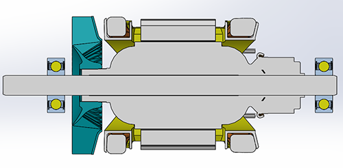
Bearing profile
In the figure, the shaft extension end bearing is the positioning end bearing, and the non-shaft extension end bearing is the floating end bearing. The two ends of the bearing bear the radial load on the shafting, while the positioning end bearing (located at the shaft extension end in this structure) bear the axial load of the shafting.
Usually the motor bearing arrangement of this structure is suitable for the motor axial radial load is not large. Common is the coupling of the load of the micro motor structure.
Post time: Jun-01-2023